Previous State of the Art
Several methods were suggested and patented over the last three decades for measuring the remaining thickness of wearable seal faces of mechanical seals. All such methods must perform two basic functions.
1. They must measure the seal face thickness while the seal face is enclosed in the seal cartridge and the cartridge is installed in a machine, and
2. They must transmit the measurement information that was acquired inside the cartridge out of the cartridge and out of the machine.
The previously patented and suggested means for measuring the seal face thickness included optical probes, electromagnetic field intensity sensors, and active ultrasonic transmitter/receiver transducer pairs. These devices must operate while submerged in the sealed fluid, where they do not fare well. Fluids interfere with the measuring mechanisms of such devices due to non-transparency, electrical conductivity, interference with electromagnetic fields, deposits, etc. Consequently, such sensors do not remain calibrated for long and, even worse, they do not survive for long in the hostile industrial environments where mechanical seals are used.
Additionally, these methods rely on electrically-powered sensors and the measurement information is transmitted out of the seal cartridge as electrical signals that require electronic amplification and conditioning. The idea of an electronic subsystem being an integral part of a mechanical seal is impractical in most industries where mechanical seals are used.
Consequently, it is not surprising that none of the patented or suggested mechanical seal monitoring methods ever became a marketable product. And this is while some of the patents are owned by large manufacturers of mechanical seals.
Our Method
Our method for monitoring mechanical seals is very different – it is free of the problems that made previous methods impractical. This patented method does not use sensors that are permanently attached to the seal, require electrical power or are affected by the sealed fluid. There is no need for recalibration or adjustments over the life of a seal, and monitoring seals with this method does not require any special skills – it is so simple that maintenance mechanics and technicians can start using it without any training.
Both the measurement of the seal face thickness and the transmission of this information out of the seal are accomplished by stress waves – a mechanical phenomenon that is unaffected by the sealed fluid and does not require electrical power.
Most importantly, the cost of adding our monitoring capability to a mechanical seal is very low compared to the cost of a mechanical seal. We believe that this technology can give a mechanical seal manufacturer a significant marketing advantage over competitors at a minimal cost.
Our method uses a wear probe that generates stress waves when it contacts a rotating component of the mechanical seal. The probe is configured to generate stress waves only if the seal face thickness is worn to below a threshold. During testing, the probe contacts the rotating component with a negligible force compared to the total force acting on the seal face. Consequently, the testing does not interfere with the sealing function of the mechanical seal.
The generated stress waves propagate through the probe and through the seal components and are detected by a stress-wave sensor temporarily placed on the machine during testing. A seal monitoring test lasts about 10 seconds and consists of checking if the sensor output increases when the probe is inserted in. The attached copy of the patent details alternative embodiments of the monitoring method, such as one for measuring the actual thickness of the seal face rather that only detecting if it is below a threshold.
The figures below illustrate schematically the operating principle of our mechanical seal monitoring method. Figure 1 shows a mechanical seal with one extra component – a wear probe that can be inserted into the seal to a depth determined by the collar on the probe. The probe can be as simple as a piece of 1/16” wire. Figure 1 shows a mechanical seal that is not being tested and its seal face is unworn.
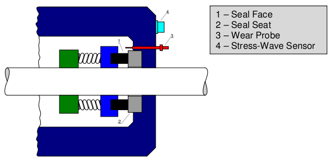
Figure 1 Seal with Unworn Seal Face – Not Being Tested
Figure 2 shows a mechanical seal with an unworn seal face that is being tested, as indicated by the probe that is inserted as far as the collar on it allows. The probe is not contacting any rotating seal components and stress waves are not being generated.
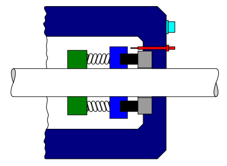
Figure 2 Seal with Unworn Seal Face – Being Tested
Figure 3 shows a mechanical seal with a worn seal face that is being tested. The tip of the wear probe now contacts a rotating component of the seal and stress waves are being generated at the point of the sliding contact between them. The stress waves propagate to the sensor and its output is now higher than what it was before the probe was inserted into the seal. The increase of sensor output is an indication that the seal face is worn beyond a threshold level.
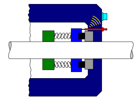
Figure 3 Seal with Worn Seal Face – Being Tested and Generating Stress Waves that Are Detected by the Sensor and Indicate that the Seal Face Is Worn
Please consult US Patent 8,527,214 System and Method for Monitoring Mechanical Seals for a more detailed description of our monitoring method and its various embodiments.